

How Does Arm Update Z N C V Registers Sub
Introduction to ARM Assembly Language
Overview of ARM Instructions

8031
A simplified block diagram of the ARM CPU and memory system is shown beneath. The ARM is a RISC machine that uses a load-store architecture, so all inputs to the ALU must come from registers, and the ALU results must exist stored in a register. In the diagram below, note the only inputs to the ALU come from registers or immediates, and the ALU output can but be stored in a register. Most data processed by the ALU will come from main memory or from a port (here, chief memory and ports are called an "external source", or ES). Since in that location are only a few registers, programs must constantly "load" operand data from an ES to a annals, and and so "store" the information back to the ES to free up the register for utilize by after instructions.
All ARM didactics codes are 32 bits, and the ARM memory bus is 32 bits. Then, each pedagogy occupies 1 retentivity location, and one "fetch" can deliver one instruction to the CPU.

The general opcode format is shown below. The bits in the opcode all accept particular assignments. The upper 4 bits are "condition codes". These four bits are combined with the ALU status bits to determine whether the education gets executed, or whether it'due south replaced with a "nop" (a nop is a "no operation" lawmaking that does not crusade any changes to registers or status bits). Embedding condition bits in the opcode, and enabling the CPU to use "conditional execution" for instructions is a special feature of the ARM processor, and will be examined in more than item afterwards.

The iii "Op1" bits and single "Op" bit form another four-scrap field that defines the education grade ('x' is a don't intendance, meaning the bit can exist a '0' or a '1', and the '-' symbol means the bit is not used). Come across the table beneath.
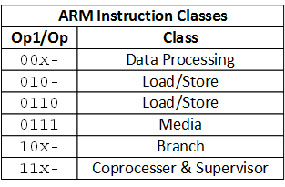
The "instruction specific fields" in the opcode vary past instruction, and there is no single definition for these 24 bits that applies to all instructions. Even so, the effigy below shows some names for these bit fields that are generally used when instructions demand a particular field. For example, the Op field generally contains 8 bits (including the four bits discussed above) that are decoded to define detail instructions. Merely, some instructions don't demand 8 bits, so often, some of those bits are unused. The S field determines whether the ALU condition bits are updated or not, and the Rn, Rd, Rs, and Rm fields generally define operand locations. Many instructions don't need all four register definitions, so those fleck fields are either unused by item instruction, or repurposed to provide other command information. Several instructions can too use immediate operands, so the lower bit fields are oftentimes repurposed to hold the immediate data.

There really isn't a strong reason to know the individual opcode for any given pedagogy, but it is helpful to understand how the opcodes are constructed, and what they control. If you are interested, you can read more near ARM teaching encoding in the ARM Architecture Reference manual starting on page A5-193.
In the cake diagram and opcode figures above, the Op and S fields provide inputs to configure the ALU, and sometimes to configure the controller state machine as well (more on that later). The Rd field provides the register accost for storing the ALU output (labelled DST_Addr in the block diagram), and the Rn and Rd fields select the input/data mux channels. In one case the ALU is configured past bits from the Op and S fields, operand data (as selected past the Rn and Rs feilds) flows through the muxes and ALU, and the ALU output is fed back to the selected destination annals in the register file. The next ascent edge of the DST_Clk signal "executes" the didactics by writing the ALU output into a register. Pretty straight forwards!
ARM has a relatively manageable prepare of "basic" instructions like Add together, Load Annals, Salve Annals, Multiply, Shift Left, And, Xor, Co-operative, and so forth. Each of these perhaps seventy instructions has a unique opcode field, and each of them apply some (or all) of the other bit fields to define which annals the source operands are stored in, which destination annals to output should exist stored in, whether an immediate operand is included, and other related information. (Once more, if an immediate operand is used, information technology will occupy some of the otherwise unused bits in the opcode). These approximately 70 basic instructions are identified past bit patterns in opcode bits 27-21 and bit four. That's 8 $.25 full, which could encode 256 different instructions (so, there is room to add more instructions should ARM ever wish to practice so).
Equally an example, the 32-scrap opcode 111000000100100010010000000000100 instructs the ARM processor to add the contents of R1 and R2, identify the result in R4, and to execute the instruction unconditionally, so update the ALU status $.25. When written as a binary number, an Opcode is also referred to as "machine code". Note that to figure out the opcode for this example, I referred to folio A8-312 of the ARM ARM (see below).

Rather than force low-level programmers to memorize machine codes, Assembler programs use mnemonics instead. The term "mnemonic" refers to a substitute memorization device that is easier to remember than the more complex detail that you're trying to memorize. For case, SOHCAHTOA is a pop mnemonic device for remembering the trigonometric relationships. In Associates language nosotros utilise mnemonics for instruction definitions, for source and destination locations, and in the case of ARM, for identifying conditional execution and whether the ALU status bits should be updated. Mnemonics take a one-to-ane relationship with the opcodes the represent – they're just easier to think. 1 of the main jobs of an Assembler program is to supercede the mnemonics with their "i…0…" opcodes… more than on that a chip later besides.
Equally an example, the 32 bit auto lawmaking higher up would have the ARM assembler mnemonic "ADDS R4, R1, R2", which is clearly more than readable and more friendly than the 111000000100100010010000000000100 machine code. The Add role of the mnemonic results in $.25 27-21 being "0000010"; the Due south appended to Add causes flake 20 to be a '1', which in plough causes the Add together pedagogy to update the ALU status bits (see the Southward flake discussion below); bits 19-sixteen are "0001" to select r1 for the destination register, and so on. Examine the motorcar lawmaking and the mnemonic, and refer to the effigy above to be sure you unsderstand how the opcode is constructed.
Firsthand Operands
No instructions use all 32 opcode bits, and in fact, many instructions apply fewer than 16. These otherwise unused $.25 can exist "overloaded" or repurposed to hold "immediate" data. In the ARM processor, immediate data is contained within the 32-scrap opcode itself. Since the opcode had to exist fetched from retentivity anyhow, these immediate operands come along for the ride, and they are "immediately" bachelor. Any educational activity that uses immediate data can become at least eight bits, and some instructions can use up to 24 bits.
Condition Lawmaking Bits
The most-significant iv bits of all instructions are "condition codes". As mentioned earlier, these 4 $.25 are combined with the ALU condition $.25 to determine whether the instruction gets executed, or whether information technology's replaced with a completely benign "nop" instruction. These iv bits are defined by the opcode. For unconditional execution, the "base of operations" educational activity mnemonic is used. For instance, ADD R4, R1, R2 volition always execute the add-on, regardless of the ALU status $.25. For conditional execution, mnemonic extensions are used to ascertain the conditions under which the educational activity should be executed. For example, to cause an Add to occur just if the previous result was not '0', the extended mnemonic ADDNE R4, R1, R2 could exist used. Adding the "NE" extension changes the four-bit status code field from "e'er execute", or "1110", to "execute if not equal" or "0001". The table below shows the condition code field, and the 2-letter mnemonic that tin can be added to an pedagogy to cause that condition to be checked.
Well-nigh all ARM instructions offer conditional execution. Checking conditions amounts to checking the ARM status annals (the ASPR) to see if the previous instruction result was null, negative, or resulted in a acquit or overflow. (The ASPR status annals is discussed later).
| Condition | Mnemonic Extension | Meaning (integer) | Meaning (Floating-indicate) | Condition Flags |
|---|---|---|---|---|
| 0000 | EQ | Equal | Equal | Z == 1 |
| 0001 | NE | Non Equal | Non Equal or unordered | Z == 0 |
| 0010 | CS | Carry Set | Greater than, equal, or unordered | C== i |
| 0011 | CC | Carry Clear | Less than | C == 0 |
| 0100 | MI | Minus, negative | Less than | N == i |
| 0101 | PL | Plus, positive or zip | Greater than, equal, or unordered | N == 0 |
| 0110 | VS | Overflow | Unordered | V == 1 |
| 0111 | VC | No overflow | Non unordered | V == 0 |
| grand | HI | Unsigned College | Greater than, or unordered | C == 1 and Z == 0 |
| 1001 | LS | Unsigned lower or aforementioned | Less than, or equal | C == 0 or Z == 1 |
| 1010 | GE | Signed greater than or equal | Greater than or equal | N == V |
| 1011 | LT | Signed less than | Less than, or unordered | N != V |
| 1100 | GT | Signed greater than | CGreater than | Z == 0 and Due north == V |
| 1101 | LE | Signed less than or equal | Less than, equal, or unordered | Z == one or N != V |
| 1110 | None (AL) | Always (unconditional) | Ever (unconditional) | Any |
Update Condition (S) Bit
The S fleck in the opcode defines whether an instruction updates the ALU status bits. Simply like with condition codes, whatsoever mnemonic tin can be extended with an S to cause the teaching to update the status $.25. Every bit examples, ADD R4, R1, R2 will load R4 with R1 + R2, opcode bit 20 volition be a '0', and the instruction volition not change the ALU status bits. The instruction mnemonic ADDS R4, R1, R2 will practice the same addition, but because the "S" is added, bit 20 volition exist a '1' and the ALU condition bits will be updated to reflect the ALU condition immediately after the didactics is executed.
General Education Format
The ARM processor supports many classes of instructions, including scrap wise logical operations like AND and XOR; arithmetics instructions like add together, subtract, compare, and multiply; flow command instructions like co-operative, breakpoint, supervisor call and exception render; information treatment instructions like shift, rotate, pack and extend; and some other miscellaneous instructions. The ARM Architecture Reference Manual defines all available instructions. To requite you a feel for the manual, the effigy below was taken from the manual to illustrate one course of instructions. The table shows the opcodes for data processing instructions (in that location are perhaps 10 other similar tables showing the opcodes for other types of instructions). The offset four bits are the condition lawmaking bits that ascertain the conditions under which the instruction volition execute. Bits 27, 26, and 25 are all '0' to indicate the data processing class, and the next 5 $.25 (24 – 20) are labeled "op". The table shows the op field, and what codes select which instruction. The next 8 bits are unused by this class of pedagogy, then they are left blank. Bits 11-7 are used for a possible 5-flake immediate operand (in this case, the immediate operand can define a shift or rotation of one of the operands – more on this afterward). Finally, bits 5 and half-dozen are used to further differential certain instructions.

| op | op2 | imm5 | Educational activity | Register |
|---|---|---|---|---|
| 0000x | - | - | Biwise AND | AND (register) |
| 0001x | - | - | Biwise Sectional OR | EOR (register) |
| 0010x | - | - | Subtract | SUB (register) |
| 0011x | - | - | Reverse Subtract | RSB (annals) |
| 0100x | - | - | Add | Add together (annals) |
| 0101x | - | - | Add together with Acquit | ADC (annals) |
| 0110x | - | - | Subtract with Conduct | SBC (register) |
| 0111x | - | - | Contrary Subtract with Carry | RSC (register) |
| 10xx0 | - | - | Information processing and miscellaneous instructions | |
| 10001 | - | - | Test | TST (annals) |
| 10011 | - | - | Test Equivalence | TEQ (register) |
| 10101 | - | - | Compare | CMP (register) |
| 10111 | - | - | Compare Negative | CMN (register) |
| 1100x | - | - | Bitwise OR | ORR (register) |
| 1101x | 00 | 00000 | Move | MOV (register,ARM) |
| - | - | non 00000 | Logical Shift Left | LSL (firsthand) |
| - | 01 | - | Logical Shift Right | LSR (firsthand) |
| - | 10 | - | Arithmetics Shift Right | ASR (immediate) |
| - | xi | 00000 | Rotate Right with Extend | RRX |
| - | - | not 00000 | Rotate Right | ROR (firsthand) |
| 1110x | - | - | Biwise Bit Articulate | BIC (register) |
| 1111x | - | - | Biwise NOT | MVN (register) |
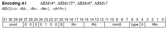
The figure below shows details of the Add instruction. Check to encounter if the ADD pedagogy is compatible with the general pedagogy format in the table above.

How Does Arm Update Z N C V Registers Sub,
Source: https://www.realdigital.org/doc/2f85bd55ef59ddbfcf64206f4421d5de
Posted by: mundywendone1953.blogspot.com
0 Response to "How Does Arm Update Z N C V Registers Sub"
Post a Comment